Please read the general information in this section before selecting the specific chassis from the compatibility matrix below. Click on the Chassis number to open a page with details about that specific configuration.
|
Compatible Chassis, Controllers, and Cables |
||||||
|
Chassis |
RAID Controller |
# of Drives |
SAS |
SATA |
Chenbro LED cables |
Chenbro SAS cables |
|
3405 |
4 |
x |
x |
1 x 26H113322-001 |
1 x 26H113215-009 | |
|
3405 |
4 |
x |
x |
1 x 26H113322-001 |
1 x 26H113215-009 | |
|
3805 |
8 |
x |
x |
2 x 26H113322-001 |
2 x 26H113215-009 | |
|
31205 |
12 |
|
x |
3 x 26H113322-001 |
3 x 26H113215-009 | |
|
31605 |
16 |
|
x |
4 x 26H113322-001 |
4 x 26H113215-009 | |
|
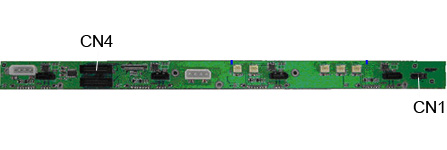
CN1 |
Connector for controller |
|
CN4 |
Backplane ID connector |
Ensure that jumpers are installed on CN1 pins 1-2, 3-4, 5-6, and 7-8 (factory default). This configures the backplane so that the activity LEDs are controlled by the disk drives.
Drive fault indication is supported via the Chenbro LED cable type 26-113322-001. To use this feature, switch the LED activity / fault indication header on the RAID controller from the default mode of “activity + fault” to “fault” only.
Note: You will need to be running firmware revision 15323 or later to implement this feature. If you are running an earlier version, you can upgrade at /support.
Press CTRL-A to enter the RAID controller BIOS; and then select SerialSelect Utility > Controller Configuration.
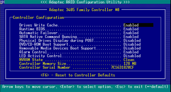
Change the setting LED Activity Control to disabled. (enabled = show activity and signal fault by blinking LED at 1Hz, disabled = indicate fault only).
Press ESC to exit, and select Yes when prompted to save changes made.
Caution: To ensure that the drives as shown in Adaptec Storage Manager are in the right order and that a failed drive is correctly identified by the red fault LED, you must set the fault connection correctly for both the mini-SAS fanout cables and the LED fault indiction cable.